Engineering and Applied Science Letter
ISSN: 2617-9709 (Online) 2617-9695 (Print)
DOI: 10.30538/psrp-easl2019.0023
Exploration of the effects of fin geometry and material properties on thermal performance of convective-radiative moving fins
G. M. Sobamowo, O. M. Kamiyo, M. O. Salami, A. A. Yinusa\(^1\)
Department of Mechanical Engineering, University of Lagos, Akoka, Lagos State, Nigeria.; (M.G.S & O.M.K; M.O.S & A.A.Y)
Grenoble INP Institute of Engineering, University Grenoble Alpes (Institute Polytechnique de Grenoble), France.; (A.A.Y)
Abstract
Keywords:
1. Introduction
Fins are extended surfaces used for heat enhancement in a thermal system. It finds numerous application in a wide variety of industries such as electronics, automobile, aerospace, thermal plant, processing plant etc [1]. It is a known fact that the activities of some industries such as chemical, nuclear and power plant quite often involves excessive generation of large amount of heat, which requires a careful method of heat dissipation. In contrast, a close look at some other industrial applications reveals that heat enhancement into the thermal system may be required. Typical example of this is found in specialized boilers and heat exchanger equipment. Consequently, increasing demand for heat enhancement devices in the industries have provoked a lot of research interest on the different types of fin design, in order to suit ever increasing industrial need. Notably among the existing fin designs are longitudinal or straight fins, radial fins, porous fins, perforated fins, composite and laminated fins to mention but few. A survey of existing literatures reveal an extensive work on the analysis of different types of fin designs. Ghasemi et al. [2], investigated a solid and porous fin with temperature dependent heat generation using differential transform method (DTM) and found out that temperature distribution is strongly dependent on the Darcy and Rayleigh number for the porous fins and the result obtained is in good agreement with the numerical result. Kosarev [3] researched on steady state thermal analysis of rectangular fins with variable thermal conductivity using grapho-analytical method and shows the possibility of solving heat transfer problems with allowance for variation of thermal conductivity of the materials with temperature. Laor and Kalman [4] worked on the performance and optimum dimension of different cooling fins with temperature dependent heat transfer coefficient using theoretical numerical analysis methods and discovered that fin efficiency of spine is greater than that longitudinal fin because shape factor has less effect on fin efficiency of longitudinal fins as compared to that of spine and the optimum dimension of any fin is attained at a point where the maximum value of dissipation per mass for any fin volume and condition is attained. Taler and Taler [5], examined the steady state and transient heat transfer through fins of complex geometry using finite element finite volume method and arrived at the conclusion that the method gave a very satisfactory result, as such can be used to determine the transient response as well as steady state efficiency of fins attached to oval and circular tubes. In the work of Sun et al. [6], collocation spectral method is used to solve the non-linear heat transfer problem in a convective-radiative rectangular fins and the result obtained when verified, shows a good agreement with the analytical solutions obtained in the literature. Ganji and Dogonchi [7], carried out analytical investigation of convective heat transfer of a longitudinal fin with temperature-dependent thermal conductivity, heat transfer coefficient and heat generation using the differential transform method (DTM), the result obtained indicates that the fin tip temperature increases with an increase in heat generation gradient and also observed that the result obtained by (DTM) is in good agreement with existing numerical data. Jasim [8] examined the transient thermal response of two dimensional composite fin using the finite element technique and observed that the larger the conductivity ratio, the faster the time to reach the steady state and further demonstrated that the efficiency of the fin increase with increase in thermal conductivity ratio. Muzychka and Yovanovich [9], developed an analytical model to compute transient thermal stresses in a biomaterial system using Laplace-numerical methods and discovered that the maximum peel stress under steady state conditions shows smaller or negative stress while the transient solution shows a very large maximum stress during initial stage of the heating process of the biomaterial component. Hatami and Ganji [10] worked on the thermal analysis of a convective-radiative fin with temperature dependent thermal properties using the collocation spectral methods. The result of the study reveals an excellent agreement with the analytical result from the literature and as such, could be used as an effective technique in handling non-linear problems in science and engineering.
Based on the existing knowledge that heat conduction rate decrease from the fin base to the tip, recent fin designed shapes are varied along the direction of conduction for optimum material utilization, which further underscore the effect of fin geometry in heat enhancement process as seen in the work of Vahabzadeh et al. [11], where analytical study of porous pin fins with variable section in fully wet conditions was conducted. The result obtained shows a concave profile having the highest efficiency while the rectangular profile having the least. Hatami and Ganji [12], establishes on similar trend, on 'optimisation of longitudinal fins with different for increasing heat transfer'. Chen and Wang [13], investigated trapezoidal fins for assessment of heat sink performance and material savings. The study reveals 0.88% difference in heat transfer ratio between trapezoidal and rectangular profiles. Mosayebidorcheh \emph{et al.} [14], carried out the transient analysis of longitudinal fins with internal heat generation, considering the effects of thermal conductivity and different profiles. A comparative study of longitudinal fins of rectangular, trapezoidal and concave parabolic with multiple non linearity was presented in the work of Torabi et al. [15], which further demonstrated the effect of geometry in heat enhancement. Torabi and Aziz [16], evaluates the thermal response and efficiency of convective-radiative T-shaped fins with temperature dependent thermal, heat transfer coefficient and surface emissivity and proved that T-shaped fins is significant in engineering applications. In a related work of Hatami and Ganji [17], thermal behaviour of longitudinal porous fins of different profiles of ceramic materials are analysed using the least square method, the result shows that fin of exponential shape with material composition(Si3 N4 ) has the highest heat transfer potentials. The effectiveness of spectral element method (SEM) is demonstrated in the study carried out by Jing et al. [18] on thermal behaviour of longitudinal porous moving fins of different profiles, a comparative analysis of the result obtained with the convex profile with the one obtained by Hatami and Ganji [17] reveals that spectral element method predicts better than the least square method. Meanwhile, there is ever increasing interest in the used of most effective method for predicting thermal responses of fins under different conditions. Hence, in this work, an attempt is made to demonstrate the effectiveness of differential transform method (DTM) in solving a thermal model with high non-linearity, by making a direct comparison with the work of Hatami and Ganji [17] and Ma et al. [18]. To the best of the Arthur's knowledge, no research work up to date has used the differential transform method (DTM) to solve heat transfer problems in a moving porous fin with irregular profiles. Hence DTM will be used to solve for the conductive, convective and radiative heat transfer in moving porous fins of three different geometries. The profiles under consideration are trapezoidal, concave parabolic and convex parabolic shapes. The physical model for the work will be presented and discussed. Also, parametric studies will be conducted to examine the effect of thermo-physical properties such as the Peclet number, porosity, surface emissivity coefficient, non-dimensional heat generation at ambient temperature, heat generation parameter, non-dimensional ambient temperature, power index of heat transfer coefficient, convective-conductive and radiative-conductive parameter and irregular shape on non-dimensional temperature distribution. Fin efficiency will also be examined and discussed.
2. Physical model and the governing equations
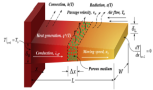
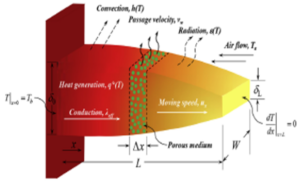
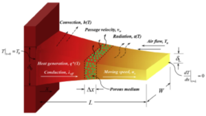
This study is focused on porous fins of trapezoidal (Figure 1), convex parabolic (Figure 2) and concave parabolic (Figure 3) profiles moving horizontally with constant velocity. The fins are exposed to convective and radiative environment. Therefore, the thermal analysis is based on the assumptions that the thermal processing of the porous fins is in a steady state and the porous medium is isotropic, homogenous and saturated with single phase fluid. The interaction between the fluid and the porous medium is governed by Darcy law, with the fin size thickness being smaller than in other dimensions, also the transverse Biot is very small, thus making temperature varying significantly only along the longitudinal direction. The surface of the porous fin is assumed grey and diffuse, with the solid and fluid being in local thermal equilibrium. The porous medium is assumed as dispersion medium, however, the heat transfer between internal pores and fluid is omitted in this work. The fin base is maintained at uniform temperature with no contact resistance, and the fin tip is insulated (adiabatic). Lastly, parameters such as heat transfer coefficient, surface emissivity, heat generation vary with temperature by the following equations:Figure 1. Trapezoidal fin profile
Figure 2. Convex fin profile
Figure 3. Concave fin profile
3. Concept and Application of differential transformation method
The differential transform method (DTM) was first used by Zhou [14]. The concept described \(f(x)\) to be an analytical function in the domain \(D\), while \(x = x_{j}\) represent any point in the domain. The Taylor's series expansion of \(f(x)\) which has its center point as \(x_{j}\) can be expressed as follows:Table 1. Transformations of some functions.
| Original function | Transformed function | |
|---|---|---|
| 1. | \(f(x) = u(x) \pm v(x)\) | \(F(x) = U(x) \pm V(x)\) |
| 2. | \(f(x) = \alpha u(x) \) | \(F(x) = \alpha U(x)\) |
| 3. | \(f(x) = \frac{dy(x)}{dx}\) | \(F(x) = (k+ 1) F(k+ 1)\) |
| 4. | \(f(x) = \frac{d^2y(x)}{sx^2}\) | \(F(x) = (k + 1)(k + 2)F(k + 2) \) |
| 5. | \(f(x) = \frac{d^n y(x)}{dx^n}\) | \(F(x) = (k + 1)(k+ 2) \dots (k + n)F(k + n)\) |
| 6. | \(f(x) = u(x)v(x)\) | \(F(k) = \sum_{l = 0}^{k} U(l)V(k - l)\) |
| 7. | \(f(x) = a (constant)\) | \(F(k) = \alpha \delta(k)\) where \( \delta(k) = \begin{cases} 1 \ if \ k = 0 \\ 0 \ if \ k \neq 0 \end{cases} \) |
| 8. | \(f(x) = x\) | \(F(k) = \delta (k - 1)\) |
| 9. | \( f(x) = x^n\) | \(F(k) = \delta (k - n)\) |
| 10. | \(f(x) = exp (\lambda x)\) | \(F(k )= \frac{\lambda^k}{k!}\) |
| 11. | \(f(x) = (1 + x)^n \) | \(F(k) = \frac{n(n -1 ) \dots (n- k + 1)}{k!}\) |
| 12. | \(f(x) = sin(\omega x + \alpha )\) | \(F(k) = \frac{\omega^k}{k!}sin\big( \frac{\pi K}{2!} + \alpha\big)\) |
| 13. | \(f(x) = cos(\omega x + \alpha )\) | \(F(k) = \frac{\omega^k}{k!}cos\big( \frac{\pi K}{2!} + \alpha\big)\) |
4. Verification
Table 2 depicted the comparative result obtained from silicon nitride of convex cross-section using the four different methods. The agreement of DTM employed in the present study with numerical as well as already published works [18], verifies the scheme.Table 2. Verification of DTM.
| X | \(\theta\) | |||
|---|---|---|---|---|
| LSM | SEN | DTM | Numerical Solution | |
| 1 | 0.885112812 | 0.885112628 | 0.848340571 | 0.84965339 |
| 0.9 | 0.886749804 | 0.886749648 | 0.8505218 | 0.852305597 |
| 0.8 | 0.891018373 | 0.891018069 | 0.85666425 | 0.85927805 |
| 0.7 | 0.897194237 | 0.897193917 | 0.866233388 | 0.869518003 |
| 0.6 | 0.904872207 | 0.904871474 | 0.878778309 | 0.882358962 |
| 0.5 | 0.913966193 | 0.913965953 | 0.893924218 | 0.897381433 |
| 0.4 | 0.924709201 | 0.924708212 | 0.911365183 | 0.914332606 |
| 0.3 | 0.937653337 | 0.937653293 | 0.93085726 | 0.933078485 |
| 0.2 | 0.9536698 | 0.953669404 | 0.952212099 | 0.953575046 |
| 0.1 | 0.97394889 | 0.973948376 | 0.975291078 | 0.975851246 |
| 0.0 | 1.0000000000 | 1.0000000000 | 1.0000000000 | 1.0000000000 |
4.1. The model efficiency determination
The following expression is used to define the efficiency (i.e., the ratio of actual heat transfer rate to the ideal heat transfer if entire fin area is maintained at the base temperature)5. Analysis of result and discussion
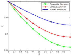
Based on the numerical research performed by Jing Ma et al. [18], the values of these physical parameters are adopted \begin{align*} \psi = 0.1, \ \ \varphi = 0.8, \ \ \alpha = 0.6, \ \ m = 2, \ \ P_{e} = 1.0, \ \ N_{cc} = 1.0, \end{align*} \begin{align*} N_{rc } = 1.0, \ \ Da = 10^{-5}, \ \ \theta_{a} = 0.3, \ \ Q_{a} = 0.1, \ \ c_{1} = c_{2} = c_{3} = 0.2. \end{align*} Thermal physical properties of the selected materials used are the same as in [18].Figure 4. Effect of geometries of Aluminium porous fins on non-dimensional temperature distribution
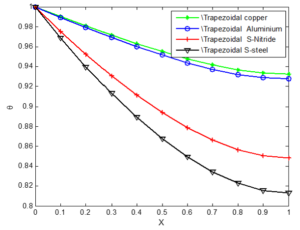
Figure 5. Effect of different materials on non-dimensional temperature distribution of fin with Trapezoidal profile
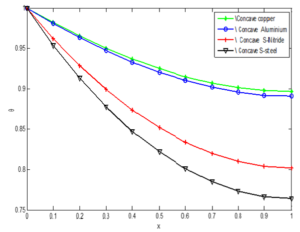
Figure 6. Effect of different materials on non-dimensional temperature distribution of fin with concave profile
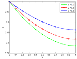
Figure 8. Effect of different value of surface emissivity on temperature distribution of trapezoidal silicon nitride porous fin
Figure 9. Effect of different values of power index of heat coefficient on temperature distribution of Concave Aluminium porous fin
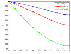
Figure 10. The effect of Peclet on the temperature distribution of a convex copper porous fins
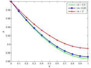
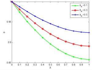
Figure 11. The effect of internal heat generation on the temperature distribution of a convex copper porous fins
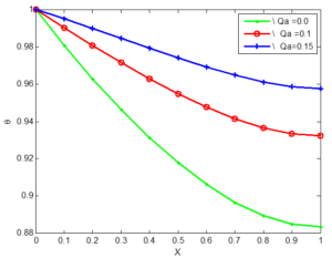
Figure 12. The effect of heat generation parameter on the temperature distribution of a convex copper porous fins
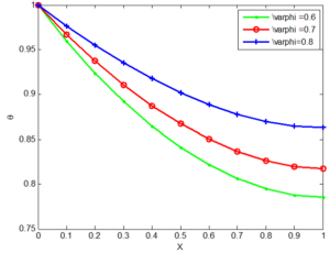
Figure 13. The effect of porosity on the non-dimensional temperature distribution for trapezoidal copper fin
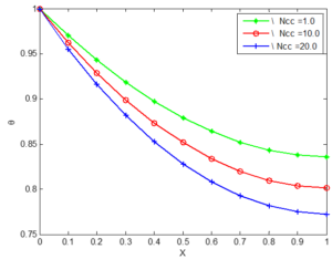
Figure 14. The effect of convective conductive parameter (Ncc) on the temperature distribution of a silicon nitride porous fin
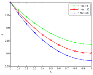
Figure 15. The effect of convective radiative parameter (Nrc) on the temperature distribution of a silicon nitride porous fin
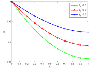
Figure 16. Non-dimensional Temperature in concave Aluminium porous fin different ambient temperature
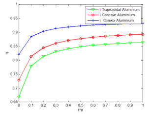
Figure 17. Variation in efficiency with Peclect number for Aluminium porous fin
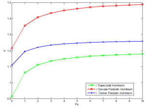
Figure 18. Variation in volume adjusted efficiency with peclect number for Aluminium porous fins
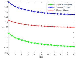
Figure 19. Variation in volume adjusted efficiency with peclect number for copper porous fins
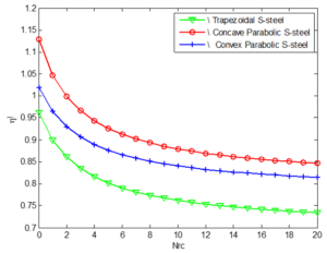
Figure 20. Variation in volume adjusted efficiency with peclect number for stainless steel porous fins
5. Conclusion
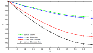
The comparative analysis carried out on the effect of materials on non-dimensional temperature distribution revealed that copper fins has the highest temperature while the stainless steel gets the lowest. More so, the fins with concave geometry gives the highest volume adjusted efficiency with increase in Peclet number while that with convex profile has the least. It is envisage that the obtained results would be useful in the future design of fins with optimum size reduction and high efficiency.Author Contributions
All authors contributed equally to the writing of this paper. All authors read and approved the final manuscript.Conflicts of Interest:
The authors declare no conflict of interest.References
- Taler, D., & Taler, J. (2014). Steady-state and transient heat transfer through fins of complex geometry. Archives of thermodynamics, 35(2), 117-133.[Google Scholor]
- Ghasemi, S. E., Valipour, P., Hatami, M., & Ganji, D. D. (2014). Heat transfer study on solid and porous convective fins with temperature-dependent heat generation using efficient analytical method. Journal of Central South University, 21(12), 4592-4598. [Google Scholor]
- Kosarev, D. A. (1965). Steady-state heat transfer through a wall with longitudinal rectangular fins and variable thermal conductivity. Journal of Engineering Physics and Thermophysics, 9(6), 482-484. [Google Scholor]
- Laor, K., & Kalman, H. (1996). Performance and optimum dimensions of different cooling fins with a temperature-dependent heat transfer coefficient. International journal of heat and mass transfer, 39(9), 1993-2003. [Google Scholor]
- Taler, D., & Taler, J. (2014). Steady-state and transient heat transfer through fins of complex geometry. Archives of thermodynamics, 35(2), 117-133. [Google Scholor]
- Sun, Y., Ma, J., Li, B. W., & Guo, Z. (2015). "Thermal analysis of a convective-radiative fin with temperature dependent properties by the collocation spectral method.," in Proceedings of CHT-15 ICHMT International Symposium on Advances in Computational Heat Transfer, New Brunswick, NJ, USA. [Google Scholor]
- Ganji, D. D., & Dogonchi, A. S. (2014). Analytical investigation of convective heat transfer of a longitudinal fin with temperature-dependent thermal conductivity, heat transfer coefficient and heat generation. International Journal of Physical Sciences, 9(21), 466-474.[Google Scholor]
- Jasim, A. M. A. (2008). Heat transfer from composite material extended surfaces heat sink. Iraqi journal of mechanical and material engineering, 8(1), 43-58. [Google Scholor]
- Muzychka, Y. S., & Yovanovich, M. M. (1996). Analytic models to compute transient thermal stresses in bimaterial systems. in International electronics packaging conference., Austin, Texas, USA.[Google Scholor]
- Hatami, M., & Ganji, D. D. (2014). Thermal behavior of longitudinal convective–radiative porous fins with different section shapes and ceramic materials (SiC and Si3N4). Ceramics International, 40(5), 6765-6775.[Google Scholor]
- Vahabzadeh, A., Ganji, D. D., & Abbasi, M. (2015). Analytical investigation of porous pin fins with variable section in fully-wet conditions. Case Studies in Thermal Engineering, 5, 1-12. [Google Scholor]
- Ganji, D. & Hatami, H. (November 2015). "Optimization of longitudinal fins with different geometries for increasing the heat transfer," in Proceedings of ISER 10th International Conference, Kuala Lumpur, Malaysia. [Google Scholor]
- Chen, H. L., & Wang, C. C. (2016). Analytical analysis and experimental verification of trapezoidal fin for assessment of heat sink performance and material saving. Applied Thermal Engineering, 98, 203-212. [Google Scholor]
- Mosayebidorcheh, S., Farzinpoor, M., & Ganji, D. D. (2014). Transient thermal analysis of longitudinal fins with internal heat generation considering temperature-dependent properties and different fin profiles. Energy conversion and management, 86, 365-370.[Google Scholor]
- Torabi, M., Aziz, A., & Zhang, K. (2013). A comparative study of longitudinal fins of rectangular, trapezoidal and concave parabolic profiles with multiple nonlinearities. Energy, 51, 243-256.[Google Scholor]
- Torabi, M., & Aziz, A. (2012). Thermal performance and efficiency of convective–radiative T-shaped fins with temperature dependent thermal conductivity, heat transfer coefficient and surface emissivity. International Communications in Heat and Mass Transfer, 39(8), 1018-1029. [Google Scholor]
- Hatami, M., & Ganji, D. D. (2014). Thermal behavior of longitudinal convective–radiative porous fins with different section shapes and ceramic materials (SiC and Si3N4). Ceramics International, 40(5), 6765-6775.[Google Scholor]
- Ma, J., Sun, Y., & Li, B. (2017). Simulation of combined conductive, convective and radiative heat transfer in moving irregular porous fins by spectral element method. International Journal of Thermal Sciences, 118, 475-487. [Google Scholor]
- Sivaraj, R., Animasaun, I. L., Olabiyi, A. S., Saleem, S., & Sandeep, N. (2018). Gyrotactic microorganisms and thermoelectric effects on the dynamics of 29 nm CuO-water nanofluid over an upper horizontal surface of paraboloid of revolution. Multidiscipline Modeling in Materials and Structures, 14(4), 695-721.[Google Scholor]
- Makinde, O. D., & Animasaun, I. L. (2016). Bioconvection in MHD nanofluid flow with nonlinear thermal radiation and quartic autocatalysis chemical reaction past an upper surface of a paraboloid of revolution. International Journal of Thermal Sciences, 109, 159-171. [Google Scholor]

