Engineering and Applied Science Letter
ISSN: 2617-9709 (Online) 2617-9695 (Print)
DOI: 10.30538/psrp-easl2021.0075
Digital high-speed data modulation techniques
Winston Tumps Ireeta\(^1\), Esther Nabadda, George Isoe
Department of Physics, Makerere University, Kampala, Uganda.; (W.T.I & E.N)
Department of Physics, Nelson Mandela University, Port Elizabeth, South Africa.; (G.I)
Abstract
Keywords:
1. Introduction
Direct modulation is very useful in high speed data transmissions though this method has several problems. The maximum bandwidth that can be modulated is just a few GHz and the maximum quantum efficiency \((\eta)\) is 100%, which places an upper limit on the slope efficiency and therefore the gain [1,2] shown in equation (1).
2. Research design
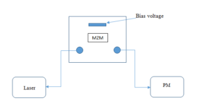
The experimental setup for the characterization of the Mach-Zehnder for different bias voltages is shown in Figure 1. When the bias voltage is varied, the power is varied so that the most suitable voltage at which transmission should be carried out is obtained. This is known as Mach Zehnder optimization.
Figure 1. Set up for Mach-Zender characterisation (performance at different bias voltages)
Figure 2. Amplitude/ Intensity modulation. A fiber optic Mach-Zehnder interferometer based on lithium niobate components is used to modulate the signal at 10GBps and 8.5GBps.
Figure 2 shows the experimental set up that was used for modulation of signals at 10GBps and 8.5GBps for a fiber optic Mach-Zehnder interferometer based on Lithium Niobate.
In amplitude modulation also known as Amplitude-shift keying (ASK), digital data is represented as variations in the amplitude of the carrier wave. For an ASK system, the binary symbol 1 is represented by transmitting a fixed-amplitude carrier wave and a fixed frequency for a bit duration of T seconds. When the signal value is 1 it means that the carrier signal will be transmitted; otherwise, a signal value of 0 will be transmitted. This such carrier signal is shown in Equation (2).
3. Result
For high speed data transmission over long distances, direct modulation may be inefficient and therefore the use of external modulation techniques for example the amplitude/ intensity and phase modulations using a Mach-Zehnder modulator.
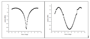
Figure 3. shows the Mach-Zehnder bias voltage characteristic curve. From the two graphs it shows that the power increases with increase in the voltages both to the negative and positive biases.
Figure 3 shows the Mach-Zehnder bias voltage characteristic curve. From the two graphs it shows that the power increases with increase in the voltages both to the negative and positive biases.
3.1. Intensity/Amplitude modulation at 8.5GBps and 10Gbps
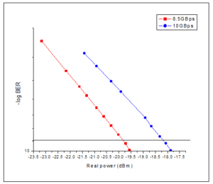
A back to back (with no fiber) transmission was performed at different rates and the sensitivity determined. The results showed better sensitivity for an 8.5Gbps compared to the 10Gbps transmission as shown in Table 1. This means that the increase of the data transmission rates exposes the signal to greater errors (penalty) and hence the reduction in sensitivity.
Table 1. Sensitivities of a Mach-Zehnder modulator at different modulation bit rates .
| Rate | 8.5Gbps | 10Gbps |
|---|---|---|
| Sensitivity(dBm) | -19.7972 | -18.1763 |
The BER was also measured for the two data transmission speeds and the results are shown in Figure 4. The increase in data transmission rates increased the power penalty.
Figure 4. B2B BER measurements at different transmission rates i.e. 8.5Gbps and 10Gbps
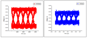
Figure 5. Eye Diagrams for 8.5Gbps and 10Gbps data transmission
Figure 5 shows the Eye diagrams for data transmissions at 8.5GBps and 10GBps. There is a closure in the eye (10Gbps) compared to the eye (8.5Gbps) which signifies increased attenuation as the rate increases. For the case of 8.5Gbps the eye is clear implying it's easier to distinguish between the zeros and ones by the receiver.
3.2. Transmission through a fiber of length of 74.91km
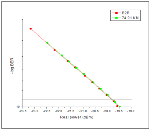
In this study, an optical fiber (74.91km) was inserted and transmission at 8.5Gbps done. The results showed a very small power penalty, implying, external modulation (amplitude modulation) enables transmission at longer distances with minimal dispersion as shown in Figure 6. This is consistent with the results of the study by Peter Winzer in 2012 [5].4. Conclusion
Very small power penalty was achieved at data transmission at a rate of 8.5GBps in a 74.91km single mode fibre which means that even with an increase in the rates to up to 100GBps, transmission at longer distances with minimal dispersion is possible.
Figure 6. BER measurements of B2B and 74.91km distance of an amplitude modulated data transmitted at 8.5Gbps
Author Contributions
All authors contributed equally to the writing of this paper. All authors read and approved the final manuscript.Conflicts of Interest
''The authors declare no conflict of interest.''References
- Proakis, J. G., & Salehi, M. (2007). Fundamentals of Communication Systems. Pearson Education India. [Google Scholor]
- Poole, I. (2008), Modulation Basics, Part1: Amplitude and Frequency Modulation, Adrio Communications Limited, Staines, UK. [Google Scholor]
- Agrell, E., & Karlsson, M. (2009). Power-efficient modulation formats in coherent transmission systems. Journal of Lightwave Technology, 27(22), 5115-5126. [Google Scholor]
- Faruque, S. (2017). Radio Frequency Modulation Made Easy. Springer International Publishing. [Google Scholor]
- Winzer, P. J. (2012). High-spectral-efficiency optical modulation formats. Journal of Lightwave Technology, 30(24), 3824-3835. [Google Scholor]

